Ray Object
The optics module uses an object orientated approach based around the Ray object. A ray is defined by its direction and its behaviour is determined by the environment it is propagating through. Hence the ray object has attributes about itself, such as its position of incidence and its wave vector, and about the surrounding media, such as the refractive indices and media interfaces functional form.
To perform refraction on a ray we must know the surface normal and the angle of incidence. Using Snell’s law we can find \(\theta_2\) and hence the rotation required to rotate the incident ray onto the refracted ray (shown in the diagram below by the hashed red arrow rotating onto the refracted black ray).
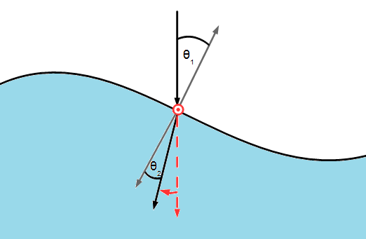
The rotation axis is the normalised cross product of the incident wave vector and the surface normal. The angle of rotation is \(\theta_{12} = \theta_1 - \theta_2 \). Hence the full transformation required is the following:
$$ R_{tot} = R_{z \to r}^{-1} R_{\theta_{12}} R_{z \to r} $$
\(R_{\theta_{12}}\) performs a rotation by \(\theta_{12}\) about the z axis this has the form:
$$ R_{\theta_{12}} = \begin{bmatrix} \cos (\theta_{12}) & \sin (\theta_{12}) & 0 \\ -\sin (\theta_{12}) & \cos (\theta_{12}) & 0 \\ 0 & 0& 1 \end{bmatrix} $$
\(R_{z \to r}\) rotates the z axis onto the rotation axis, r. To form this transform let us consider rotating a unit vector \(a\) onto another \(b\). The axis of rotation is along \(x = a \times b\). Using Rodrigues’ rotation formula in its matrix form to rotate \(a\) about \(x\) by an angle \(\theta\):
$$ \mathbf{b} = \left( I + \sin(\theta) X + (1 - \cos(\theta)) X^2 \right) \mathbf{a} $$
Where \(X\) is the cross-product matrix for \(x\) defined by
$$ X = \frac{1}{\left| x \right|}\begin{bmatrix} 0 & -x_3 & x_2 \\ x_3 & 0 & -x_1 \\ -x_2 & x_1 & 0 \end{bmatrix} $$
Also \( \left| x \right| = \sin(\theta)\) and \(a \cdot b = \cos(\theta) \)
Hence replacing \(a\) by a unit vector pointing along z and \(b\) by the normalised cross product of the unit surface normal and the unit incident wave vector, we obtain the required rotation matrix.
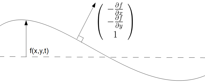
With total rotation matrix formed we can calculate the position of the refracted rays at the base of the refracting medium. This is simply done by enlarging the length of the vector until the z component is equal to the distance to the bottom, \(h+f(x,y)\). The refracted ray position can then be read off from the x and y components of the vector (plus the rays initial position).
Ray Object
Ray(x,y,f,dfdx,dfdy,h,n_arr) (__init__ function)
Parameters:
x,y: numpy arrays
Numpy arrays containg the x and y coordinates of the rays before refraction
f, dfdx, dfdy: functions
f: A function of x, y and t which gives the displacement of the second mediums surface
dfdx: A function of x, y and t which gives the partial differential of f along x
dfdy: A function of x, y and t which gives the partial differential of f along y
These are used to compute the unit normal and the height the ray must descend to reach the bottom of the second medium
n_arr: list of floats
A list of two floats, the first being the refractive index of the first medium and the second that of the second medium
h: height
The height of the second medium, the incident light rays which refract will be traced until they reach this height
findnormal(self,t)
Finds the normalised normal vector at position of the incident ray
Parameters:
t: numpy array
A numpy array with the time coordinates for which a refracted image will be displayed
snellsangle(self)
Calculates the angle of refraction via Snell’s law
transformation_matrix(self)
Calculates the rotation matrix required to rotate the incident ray onto the refracted ray
refract(self,t)
Computes the refracted ray positions using the rotation matrix
Parameters:
t: numpy array
A numpy array with the time coordinates for which a refracted image will be displayed